Fitting an MGA/MGB Crown Wheel and Pinion to T Final Drive
With thanks to Ian Frost
The standard ratio fitted to the TF is too low for today’s driving. The ratio I changed from was 4.875:1. First gear was too low to be of any use and touring at 100Kph at 4000 plus rpm is not pleasant nor is it good for your engine.
I currently have a complete MGB final drive (banjo type) fitted to my TF 1500 with a 3.9 ratio and it drives very well. I only fitted this as after reading the blogs on the internet that make out that the job of fitting the MGA gears into the TF housing is complicated, and may take some time. As it turned out I could have got it done in a day (if I had the energy) and had all the parts on hand.
I would not recommend the 3.9 be fitted to a 1250 as it would be a step too far. I believe the 4.3 is the sweet spot.
Below is a table showing speed in top gear in 500 rev increments for the three different ratios we are discussing in this paper. (approx and rounded)
Speed in Top Gear (Kilometers an Hour)
| RPM | 4.875 | 4.3 | 3.9 |
| 1000 | 24 | 27 | 30 |
| 1500 | 36 | 41 | 45 |
| 2000 | 48 | 55 | 60 |
| 2500 | 60 | 68 | 75 |
| 3000 | 72 | 82 | 90 |
| 3500 | 84 | 96 | 105 |
| 4000 | 96 | 109 | 120 |
| 4500 | 108 | 123 | 135 |
Required Tools
The tools you will require for this job are not extensive nor are they expensive (if you don’t have them on hand.)
- Veinier gauge, dial gauge and feeler gauges.
- Hand tools as in sockets, spanners, punches, tin snips.
- Bearing puller (less than $40 on eBay)
- Gasket paper and wad punch.
- Sheets of shim steel 0.010”, 0.005” and o.003”.
Components/parts Needed for this Ratio Swap
- MGA/MGB front and rear pinion bearings.
- Selection of pinion preload shims
- MGTF carrier bearings
- MGA or MGB final drive centre from banjo style rear axle with the ratio of your choice.
Procedure
Follow the instructions in the workshop manual for removing the components if you are not sure how to go about it. The TF manual will do.
Before dismantling the MGA centre inspect the crownwheel and pinion for damage and record the backlash.
Remove the carrier assembly from the housing and remove the crownwheel from it.
Remove the pinion from the housing.
Keep the crownwheel, the pinion, the pinion bearings, the pinion spacer and the pinion flange and nut. Put the remainder of the MGA/B parts away.
Mount your TF final drive (with axles and backing plates removed and oil drained) vertical in a vice with the nuts that hold it together facing up.
Remove the nuts and washers that hold the two halves together.
There are two threaded holes in the case flange that allow you to screw bolts into and act as a puller to remove the case half.
When the case half comes away retrieve the spacers from the case where the carrier bearing live.
The carrier along with the crownwheel can now be lifted out.
Remove the pinion and the spacer and put it away.
Fit the MGA/B pinion into the TF case along with the spacer without any preload shims. Leave the old bearing cones in place.
With the pinion nut run up you will find the pinion will move in and out of the case. This is because the bearing cones in the TF case are closer together than in the MGA/B case. Measure this axial movement with the veinier or the dial gauge and record it.
Remove the pinion from the case.
The pinion bearing now has to be pressed off the pinion. This has to be done on a hydraulic workshop press as it will be very tight.
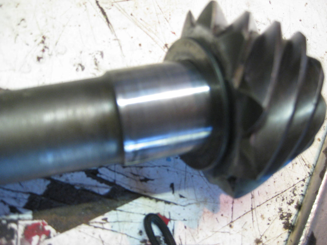
Linished pinion with machined spacer ready for bearing
Linish by hand the pinion shaft where the rear bearing mounts. You only have to remove about 0.001” to go from an interference fit to a line fit, this will not take very long, check the fit often. This allows you to fit the new bearing using a pipe and hammer. When you fit the new bearing leave the pinion spacer shim out. Measure the spacer and fit the bearing so the distance between the bearing and the pinion head is about 0.020” less than the spacer.
The reason for linishing the pinion is to allow the drive flange nut to pull the pinion into the bearing. This changes the depth of mesh and it’s the only way we can find the correct pinion position without special measuring jigs. (Which don’t exist for this job)
Remove the bearing cones from the case. The rear cone can be removed with a punch and hammer. The front cone is best removed with a two legged puller as the case won’t allow you to swing a hammer in the confined space.
Now cut shims from your sheet of shim steel so as they add up just a bit bigger than the endfloat of the pinion you previously recorded. These shims are going in before the front bearing cone.
This will space the bearings out to be the same spacing as the MGA/B case.
It is best to pull the new cones into the case using some threaded rod and parts of the old bearings. Care must be taken to start the large cone inside the case as it is very easy to cock it.
Now that the new bearings are in place fit the pinion to the case without the spacer. Run the flange nut up just so as there is no axial movement of the pinion.
Remove the TF crownwheel from the TF carrier. Put it away with the TF pinion.
Fit the new carrier bearings and bolt the MGA/B crownwheel to the carrier.
Drop the carrier into the case with the original spacer and a shim you have cut. Start with a 0.010” shim. Add shims until you feel some backlash.
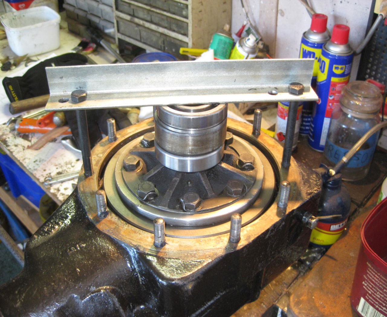
Now with the home made tool in the picture below (or threaded bar with the differential pinions removed) pull the carrier down square to check backlash.
If it’s a used crownwheel and pinion you should aim to be close to your recorded backlash measurement you took before you dismantled the MGA/B case.
Rotate the pinion with the socket and bar and feel for a smooth rotation.
Remove the carrier and lightly coat six or seven teeth of the crownwheel with marking paste (a zinc based paste is good for this. Use haemorrhoid cream mixed with a little acrylic paint.( I got this tip from a YouTube clip)
Fit the carrier back into the case and clamp down and rotate the pinion both directions whilst putting a load onto the crownwheel with a gloved hand.
Remove the carrier and inspect the mark.
With a used crownwheel and pinion you should aim for a contact exactly as it was.
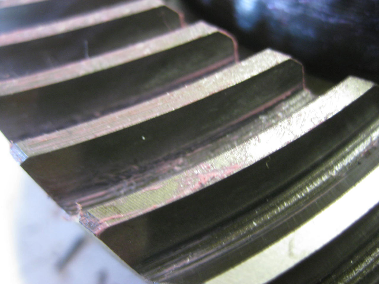
Tooth contact marking can only be as good as it was when using used parts
If the mark is on the tow on one side of the tooth and on the heel on the other side of the same tooth, the pinion needs to be pulled further away from the crownwheel. Do this no more than one flat of the drive flange nut each time.
Check backlash and adjust your shim stack if necessary, and take a new mark.
This can be tedious but it is best to do it in small increments.
When the correct mark is achieved with the backlash correct remove the pinion and measure the clearance between the pinion and the bearing.
There is no shim supplied this thickness from MG spares so you can have your shim ground down to suit or search down a suitable shim.
Fit the shim and the pinion bearing onto the pinion and fit the pinion with spacer with several pre-load shims to the case. Follow the workshop manual until you achieve the correct pre-load.
Place the carrier in to the case.
The other case half can now be fitted with the original carrier bearing spacer and bolted down lightly and evenly. Check with feeler gauges to ensure it is the same all around the flange.
This procedure is spelt out in the workshop manual. By adding or subtracting the thickness of the spacer /shims in the upper case half you just fitted you should aim for a gap of 0.008” if the gasket is 0.005”. I.e. The gap should be 0.003”plus the thickness of the gasket you are using.
The preload measurement should be slightly higher when the case halves are bolted together as the carrier bearing preload is now added to the pinion preload.
Remove the drive flange and fit the oil seal.
In closing I have now fitted the original TF rear axle with the 4:3 ratio and I am pleased with the result.
If you wish to attempt this conversion and you are unsure of the process please reach out to Seth and he’ll put you in touch: [email protected].
Dean Lovig
23 January, 2018 (10:05 PM)
Good evening,
I’m in the MGCC in Melbourne and am looking for a 4.3:1 diff to replace the 5.125:1 that is fitted to my MG TD. Can you ask your membership base if any of them have the spare diff sitting in the garage that has been kept for that “just in case” moment.
Please reply to Seth at [email protected] and he’ll put you in touch.
mgcarclubsydney
30 January, 2018 (8:47 AM)
Hi Dean,
I’ll get in touch and see if we can set up a ‘wanted’ ad for you. Will send an email.
Cheers,
Seth.
jon
25 December, 2020 (2:20 PM)
i have a 51 mgtd and an mgb with overdrive….i would like to use the mgb to upgrade my td….are there any conversions that would work for this….brakes…steering…rear axle ratios… engine size… trans…etc…..thanks for any advice or help you can give